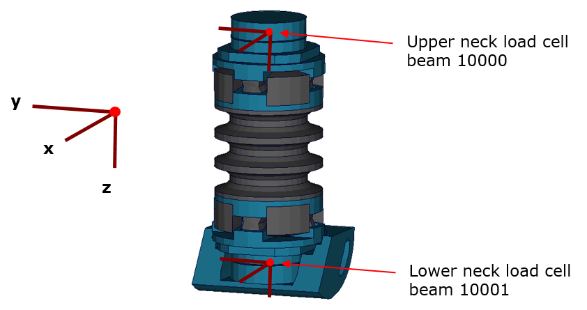
Upper and Lower Neck Load Cell
All load cells in the model are defined in the same way. They are modeled using a discrete beam in combination with a local coordinate system. The results of the discrete beam are printed in the ELOUT file with respect to the local coordinate system. The local axes to evaluate the results of the beam are listed in the table below.
| Item | Component in ELOUT File |
|---|---|
| Local X-Force | axial |
| Local Y-Force | shear-s |
| Local Z-Force | shear-t |
| Local X-Moment | torsion |
| Local Y-Moment | moment-s |
| Local Z-Moment | moment-t |

Upper and lower Neck Load Cells
| Item | Beam ID | Label | Channels in physical dummy |
|---|---|---|---|
| Upper Neck Load Cell | 10000 | NECKUP00WS | Six-channel load cell |
| Lower Neck Load Cell | 10001 | NECKLO00WS | Six-channel load cell |
The neck load cells are six-channel load cells. This means that the forces and the moments in each direction of axis can be evaluated in the hardware.
