Arm Tests
The arm is mounted on the test box using the original shoulder load cell. In most of the tests, the notch of the arm is in the 40 degree position. The load cell is then rotated so that the arm in each test is in a vertical position. For a different notch of the arm adjustment, only the shoulder load cell is rotated. The figure below shows the three pendulum positions used for the arm tests. In the table below all test setup configurations are listed.
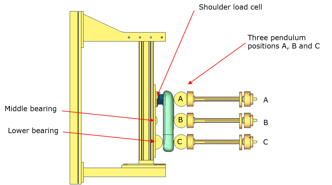
Half arm test setup with all pendulum positions
| Test | Shoulder Load Cell Angle | Target Point | Velocities |
|---|---|---|---|
| 1 | 48 degree | A | 2 m/s and 4 m/s |
| 2 | 48 degree | B | 2 m/s and 4 m/s |
| 3 | 48 degree | C | 2 m/s and 4 m/s |
| 4 | 8 degree | B | 2 m/s and 4 m/s |
| 5 | 8 degree, middle bearing modified | B | 4 m/s and 6 m/s |
Test number 5 is done by using a reduced distance between the middle bearing and the arm. Target is that the arm hits the middle bearing after bending.
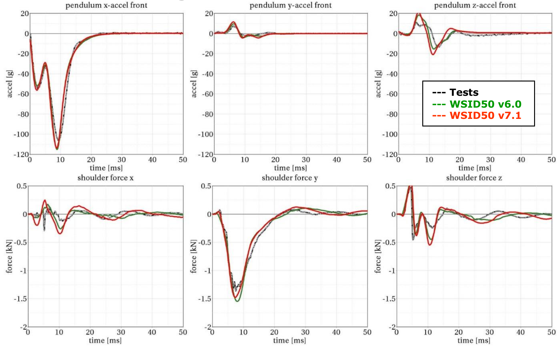
The results of all tests are shown in the following figures:
Results - Target point A, 2 m/s velocity, 48 degree load cell position
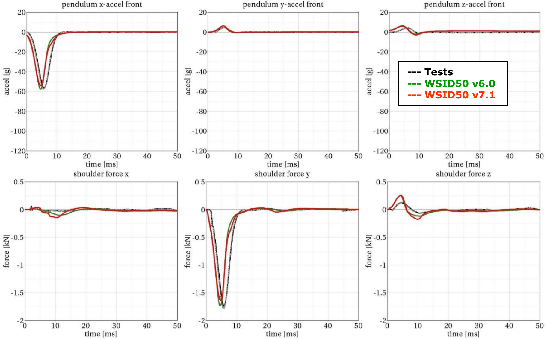
Results - Target point A, 4 m/s velocity, 48 degree load cell position
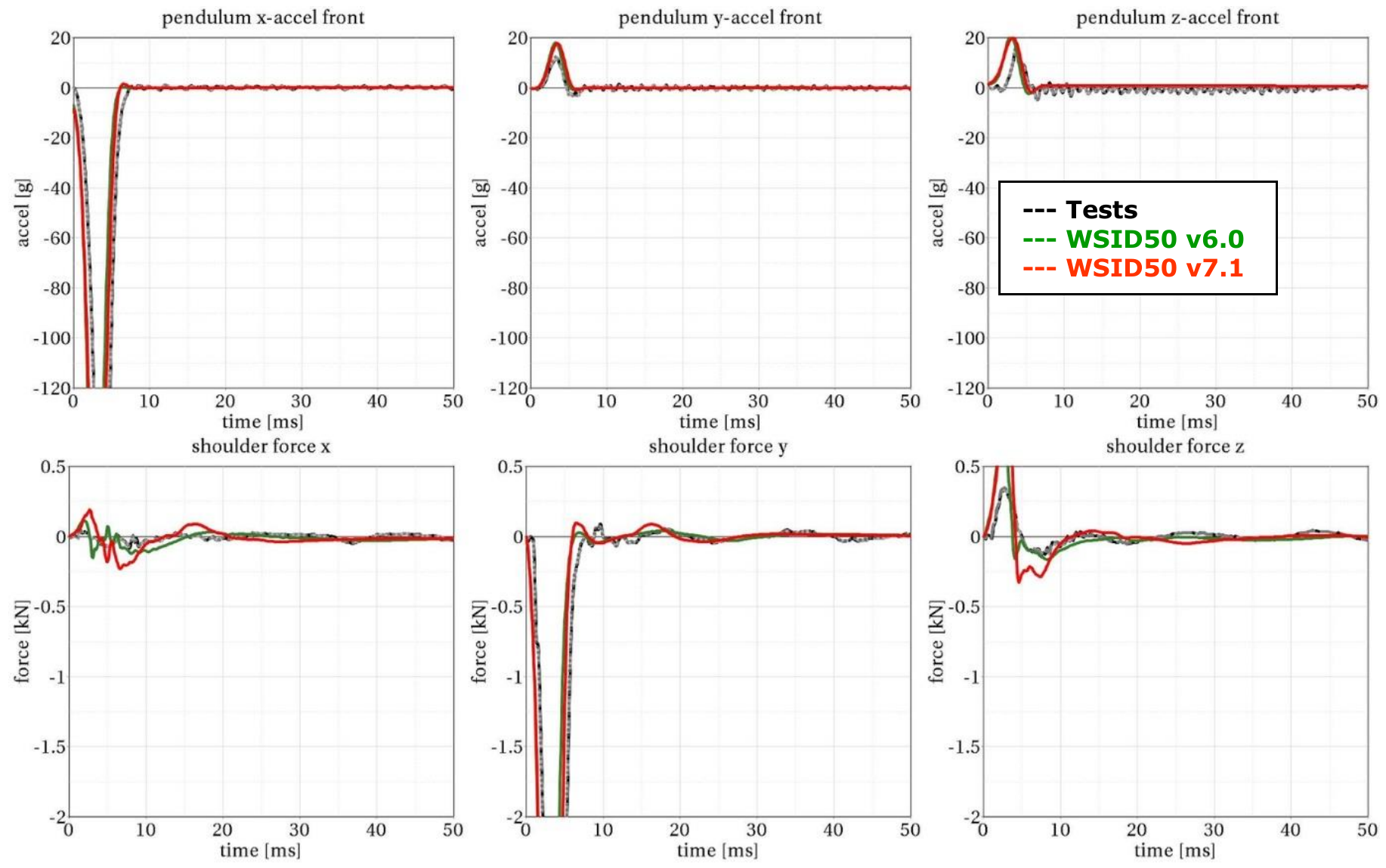
Results - Target point B, 2 m/s velocity, 48 degree load cell position
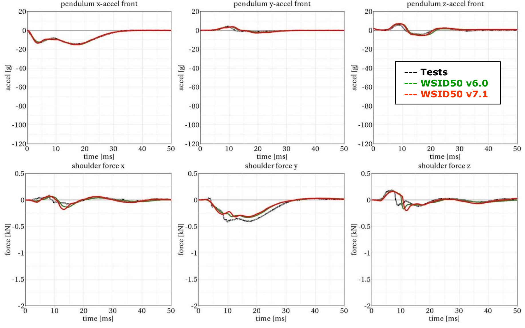
Results - Target point B, 4 m/s velocity, 48 degree load cell position
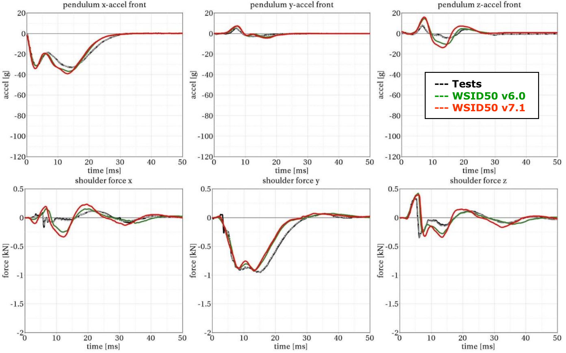
Results - Target point C, 2 m/s velocity, 48 degree load cell position
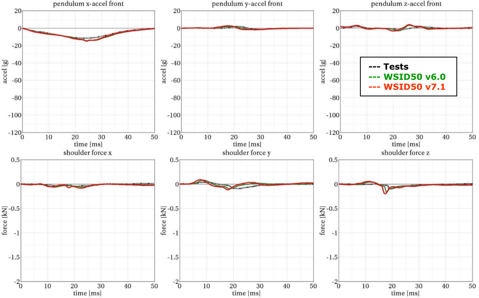
Results - Target point C, 4 m/s velocity, 48 degree load cell position
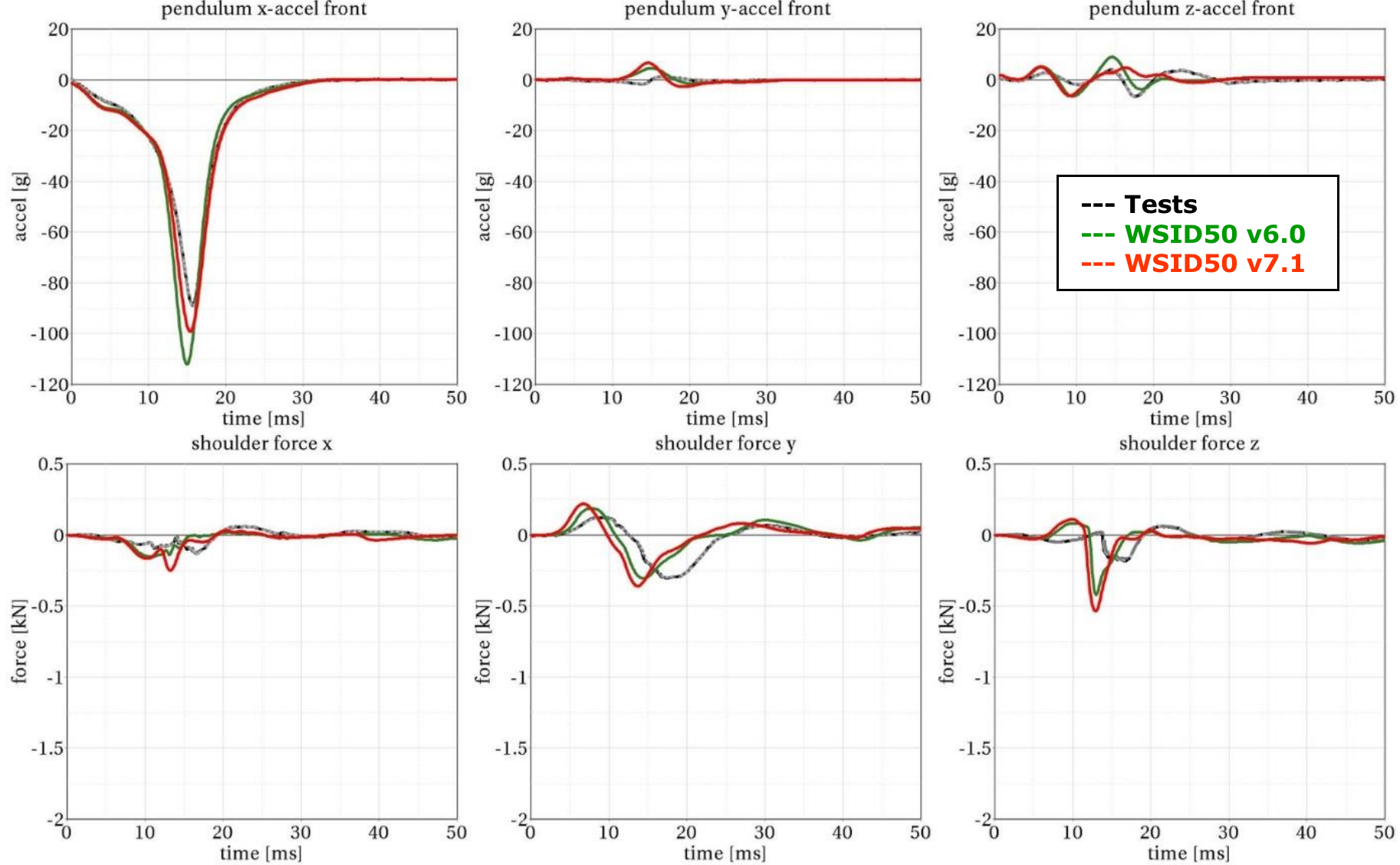
Results - Target point B, 2 m/s velocity, 8 degree load cell position
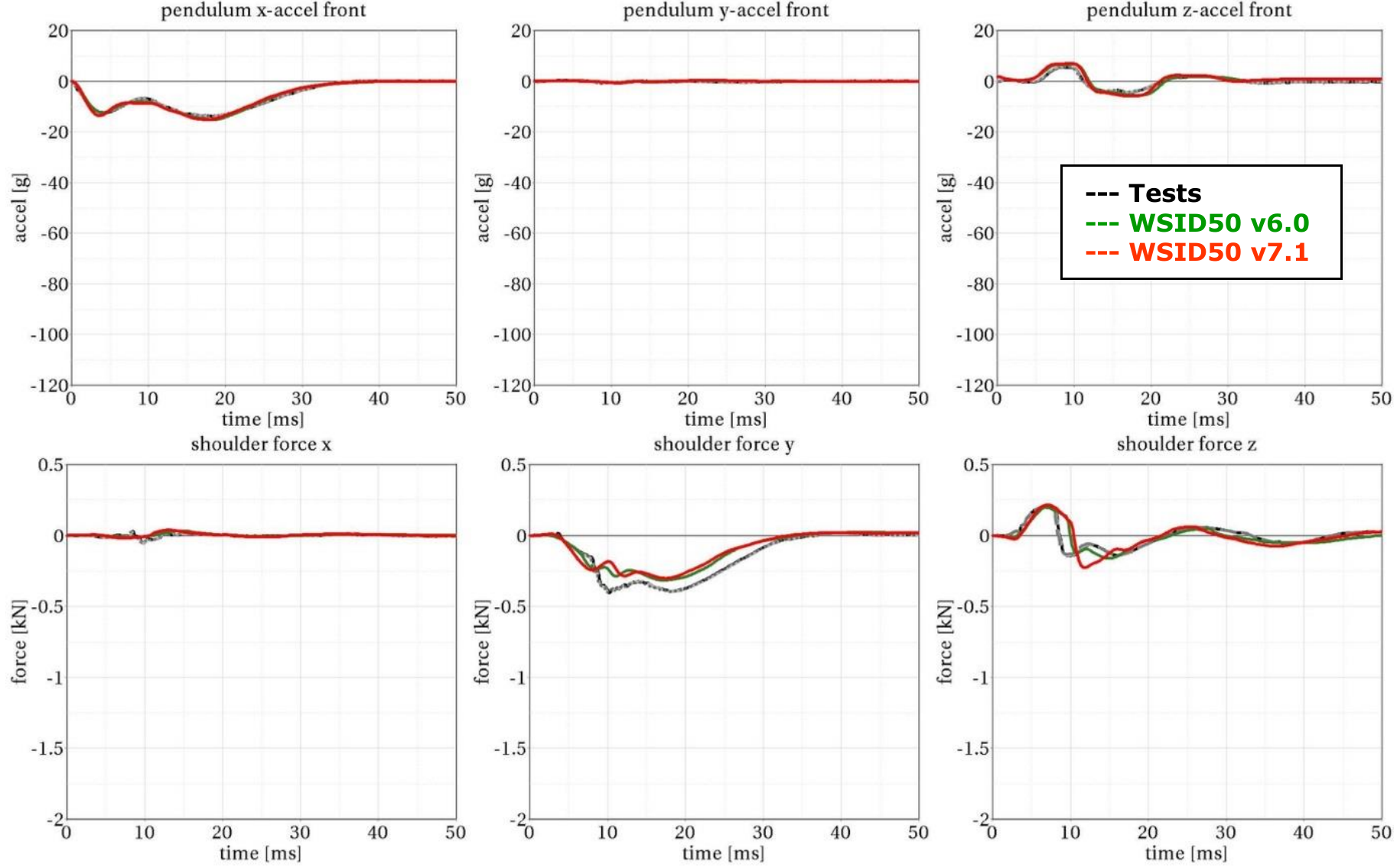
Results - Target point B, 4 m/s velocity, 8 degree load cell position
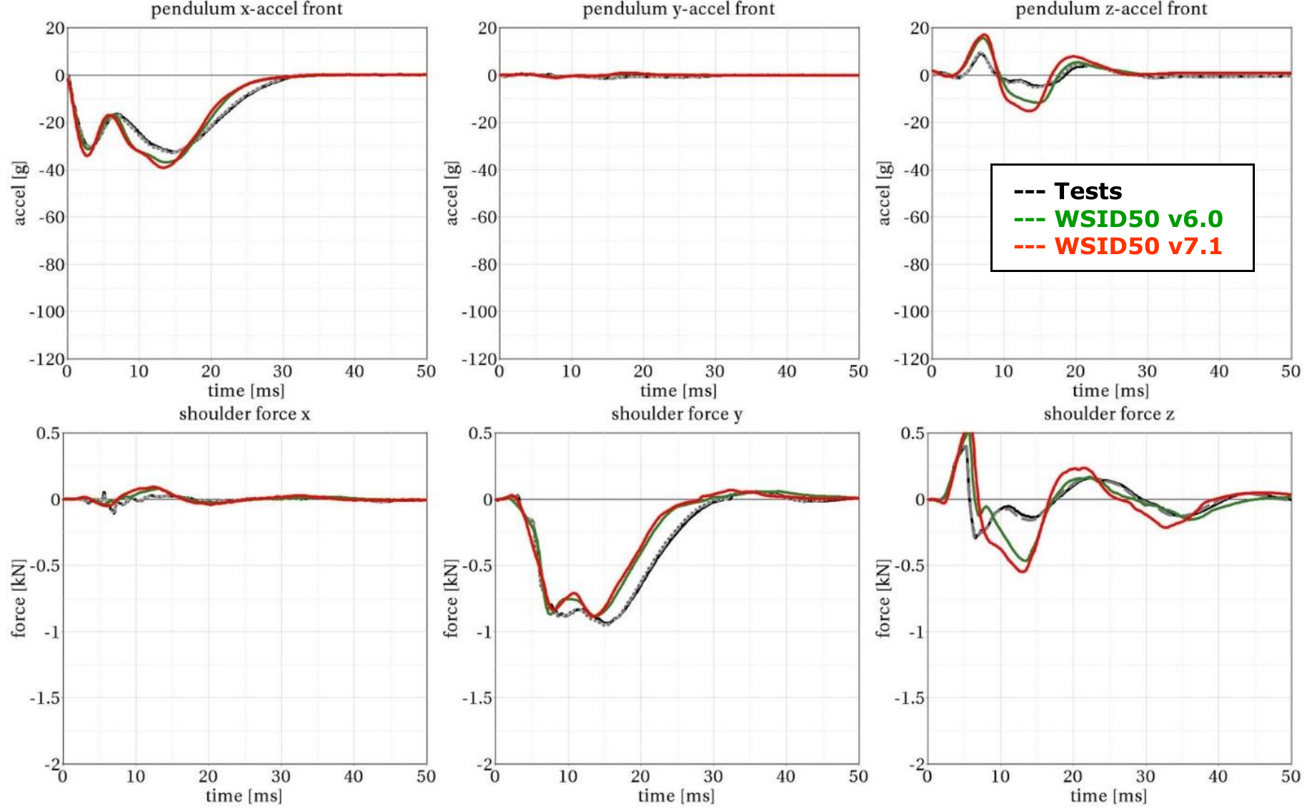
Results - Target point B, 4 m/s velocity, 48 degree load cell position and modified middle bearing
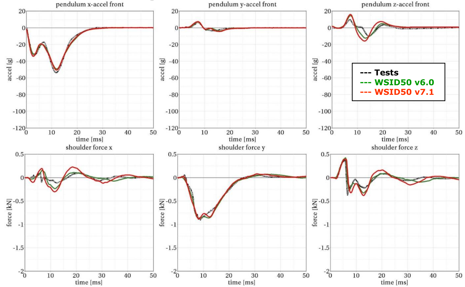
Results - Target point B, 6 m/s velocity, 48 degree load cell position and modified middle bearing
