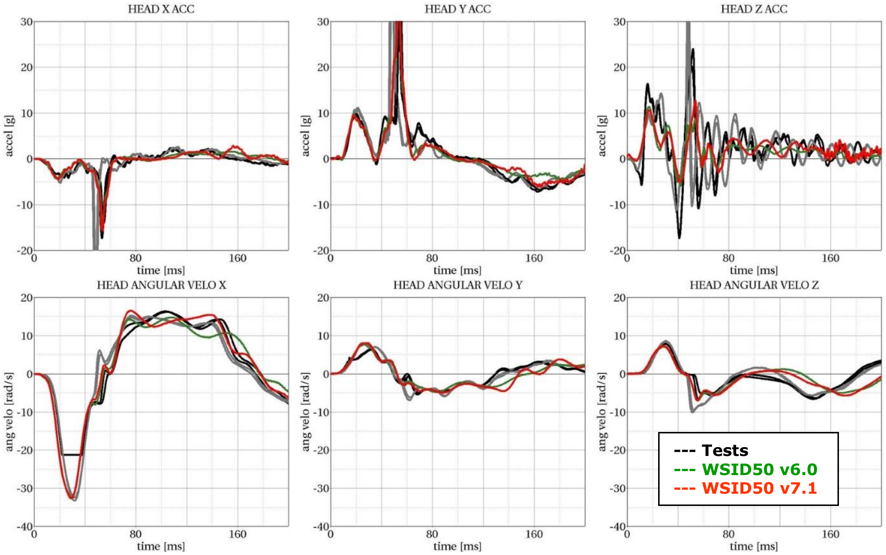
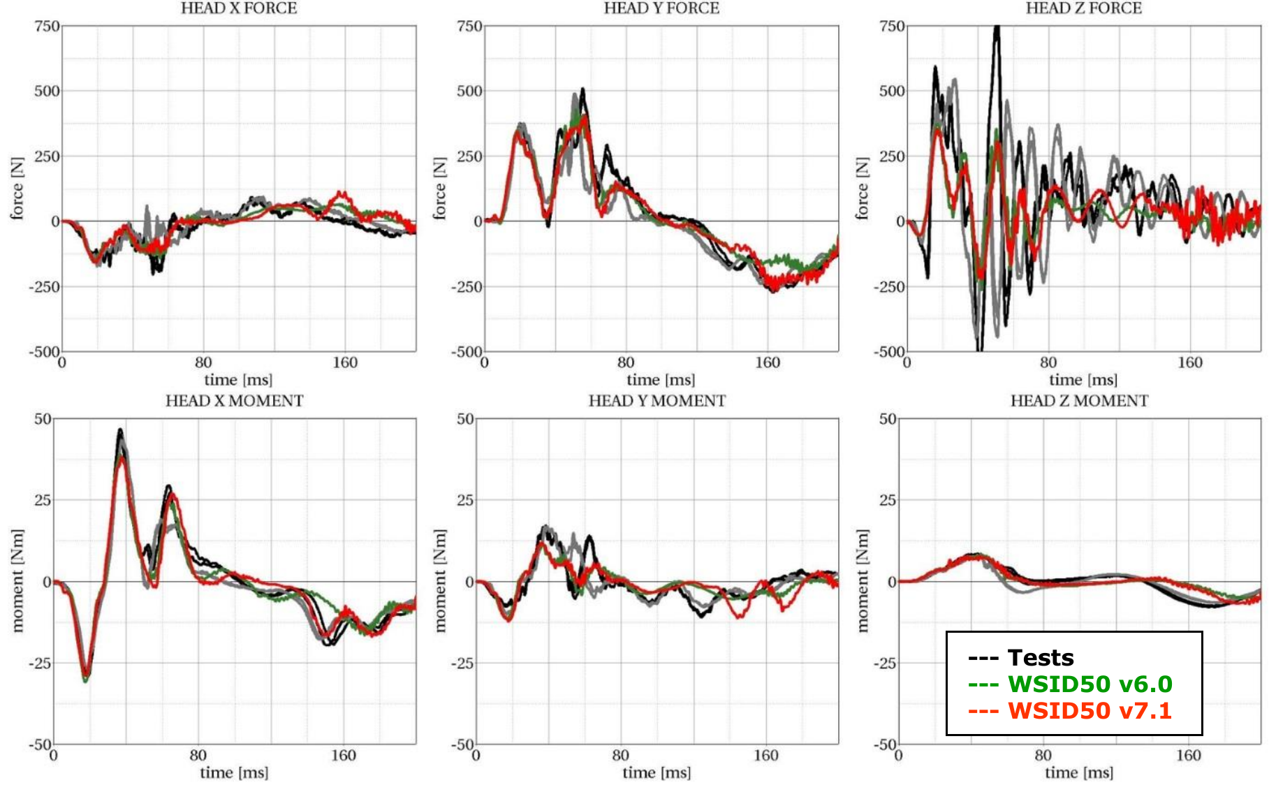
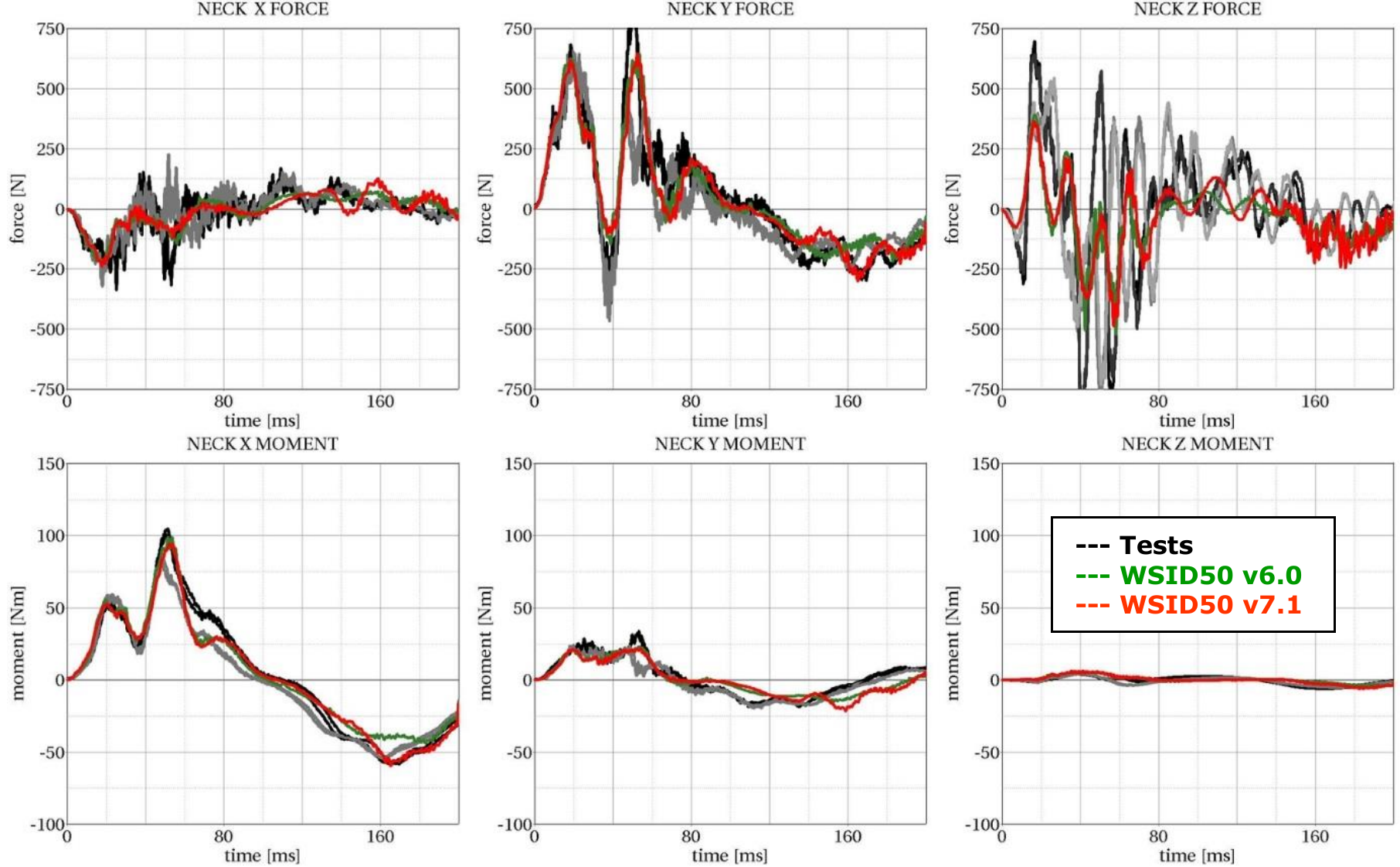
Head Neck Tests
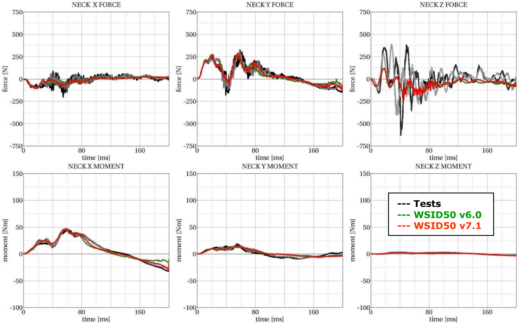
This test is built to validate the neck unit in use of the mounted head assembly. The test setup is depicted in the Figure 19 below. The loads on the sled are defined to get signals which are similar to the neck signals in a full car crash.
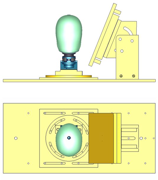
Head-neck test setup -- 90 degree, side and top view
The oblique plate is adapted only as a guide for the neck in the highest pulses. Two different pulses are tested for a 90 degree configuration as depicted in Figure 19 and the same two pulses for a 75 degree configuration of the component. The configurations are listed in the table below:
| Test | Load Angle | Pulse |
|---|---|---|
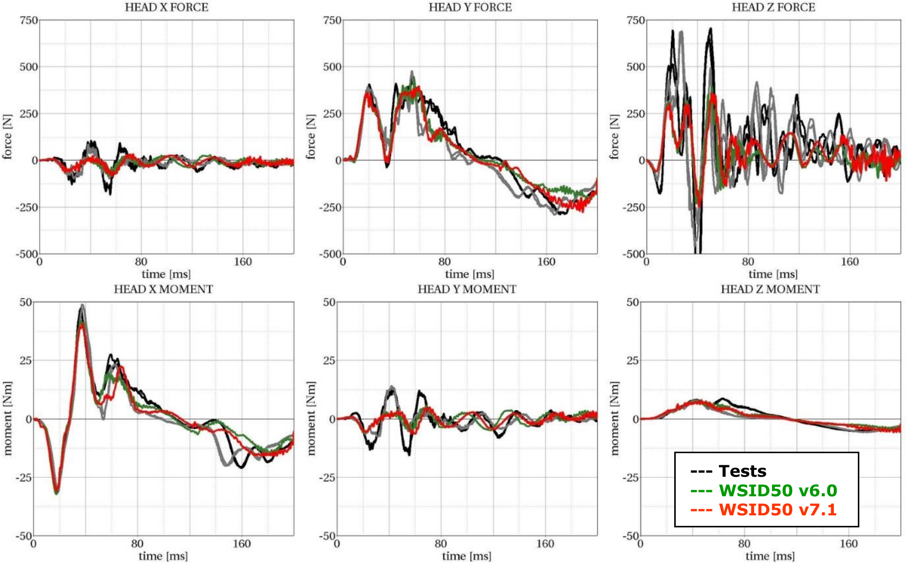
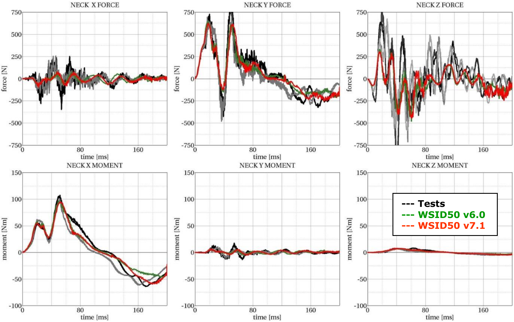
| 1 | 90 degree | 20 g triangular pulse |
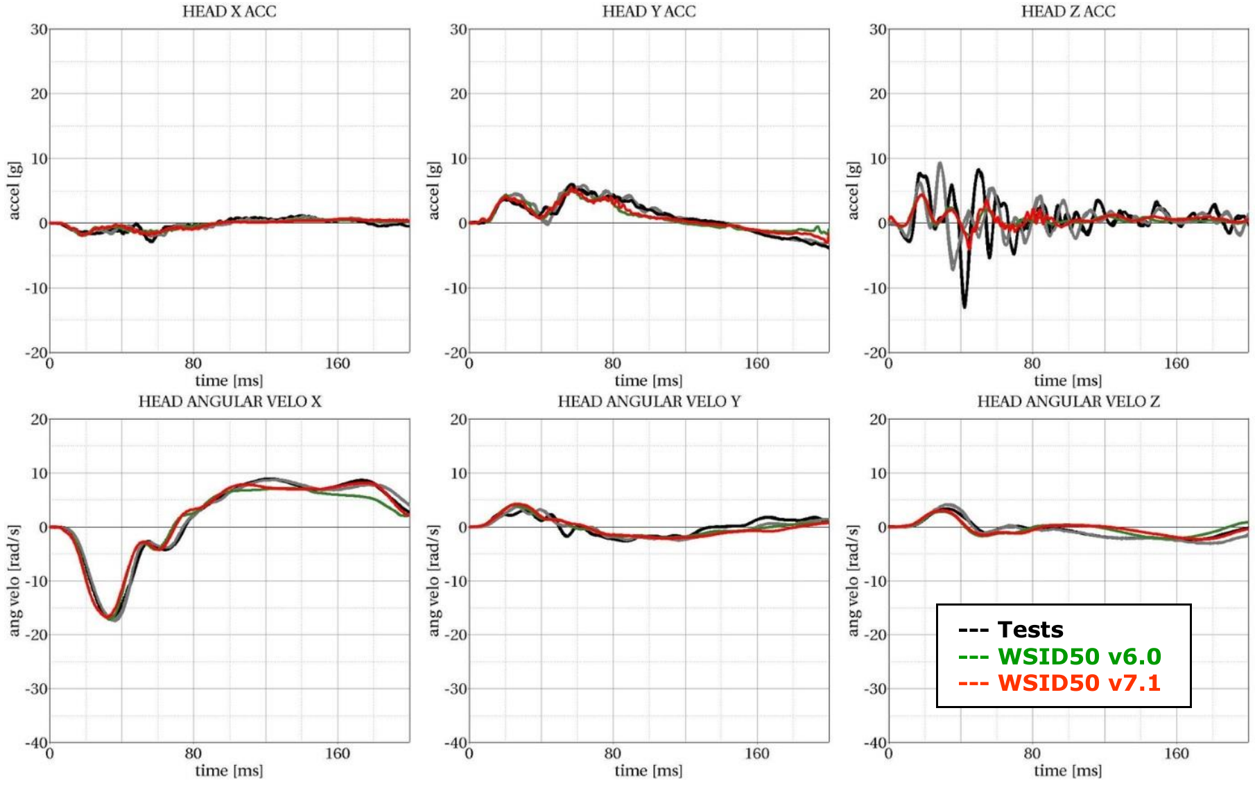
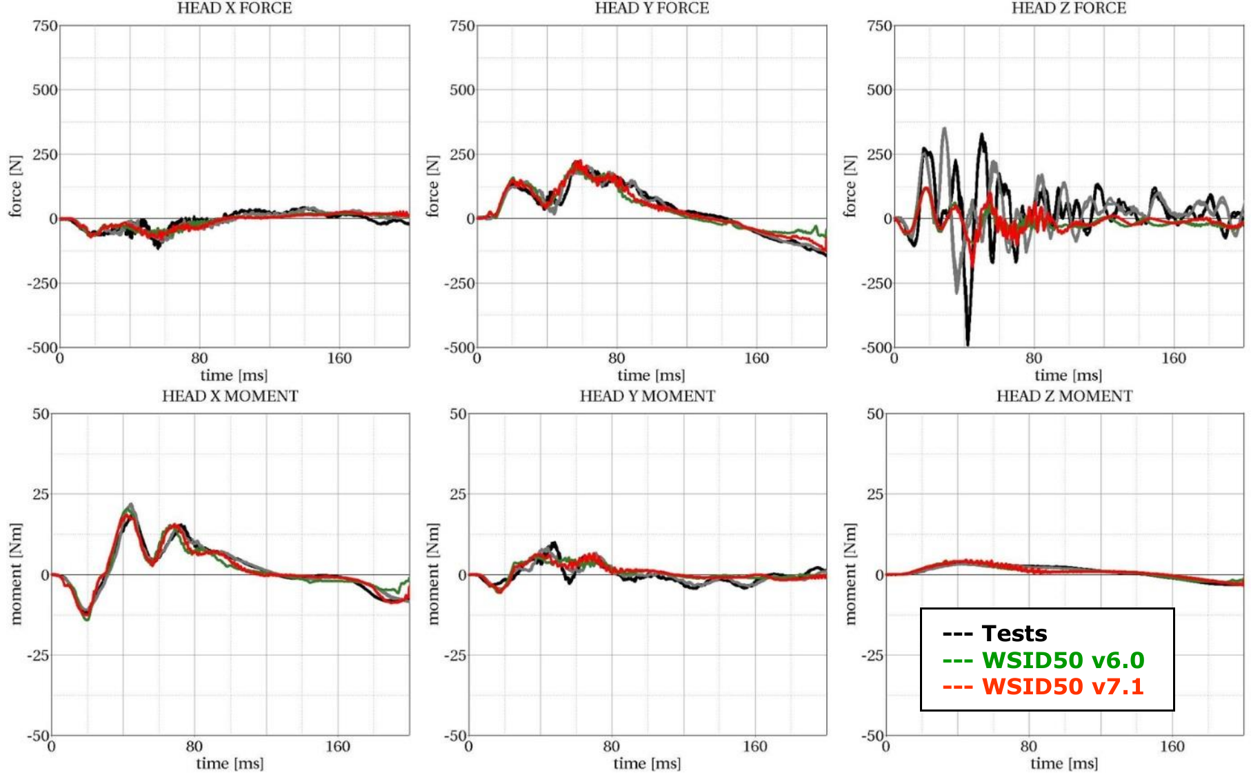
| 2 | 90 degree | 35 g triangular pulse |
| 3 | 75 degree | 20 g triangular pulse |
| 4 | 75 degree | 35 g triangular pulse |
Results of 90 degree, 20g configuration:
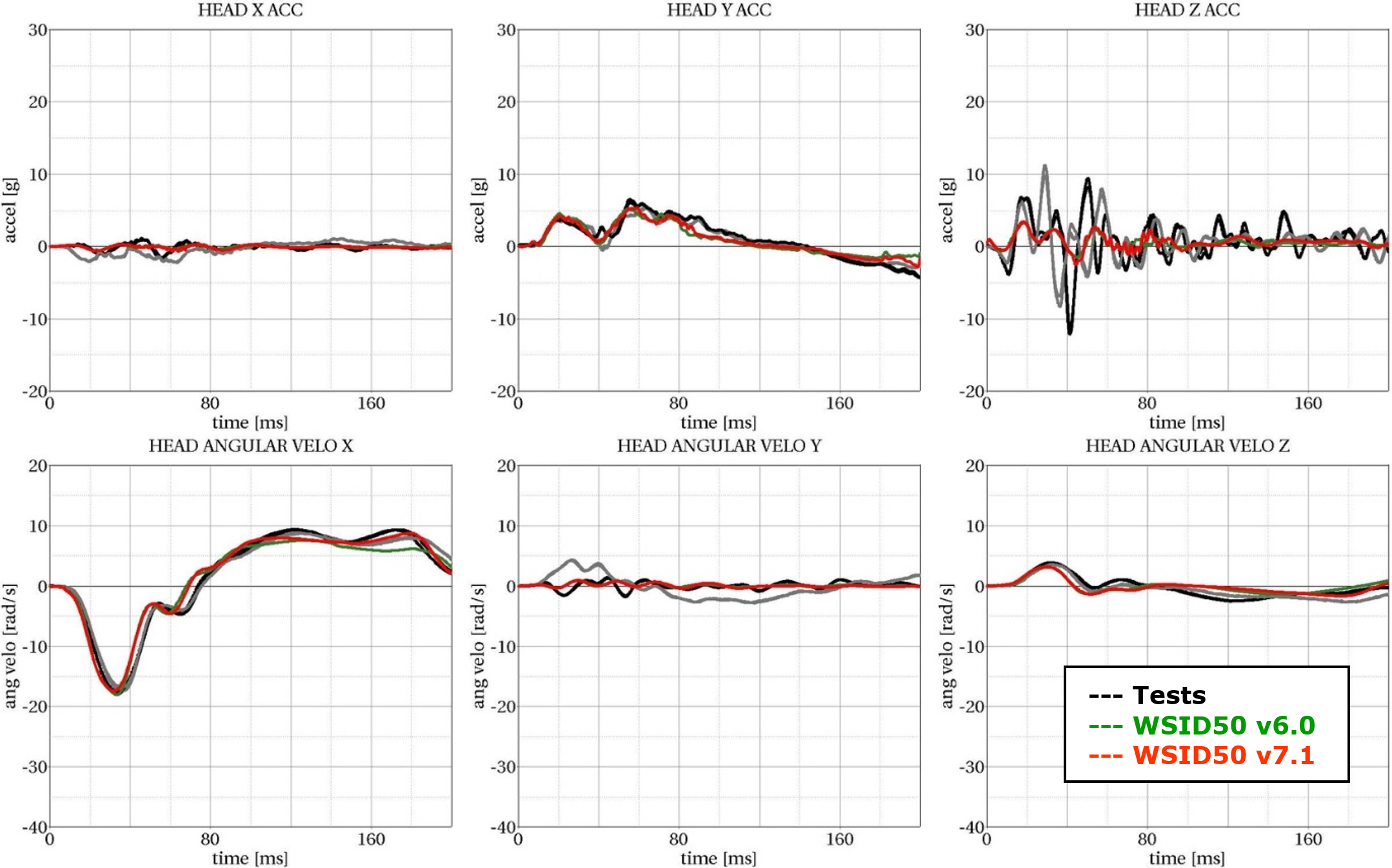
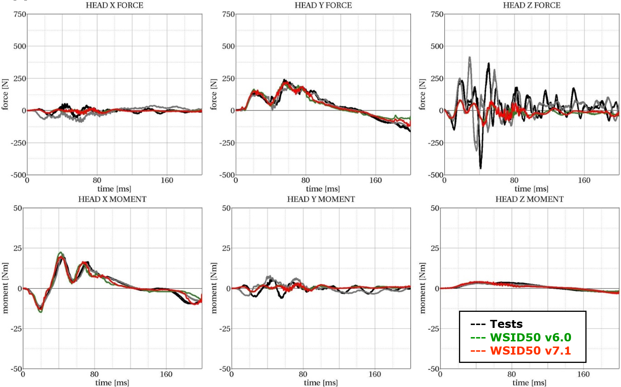
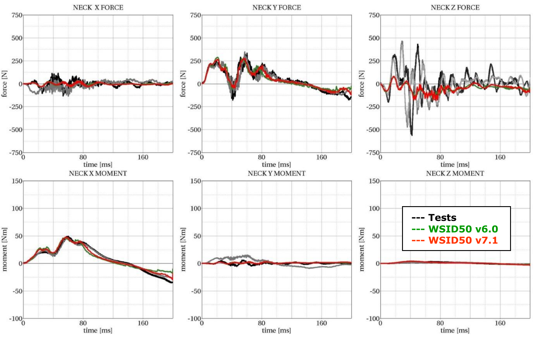
Results of 90 degree, 35g configuration:
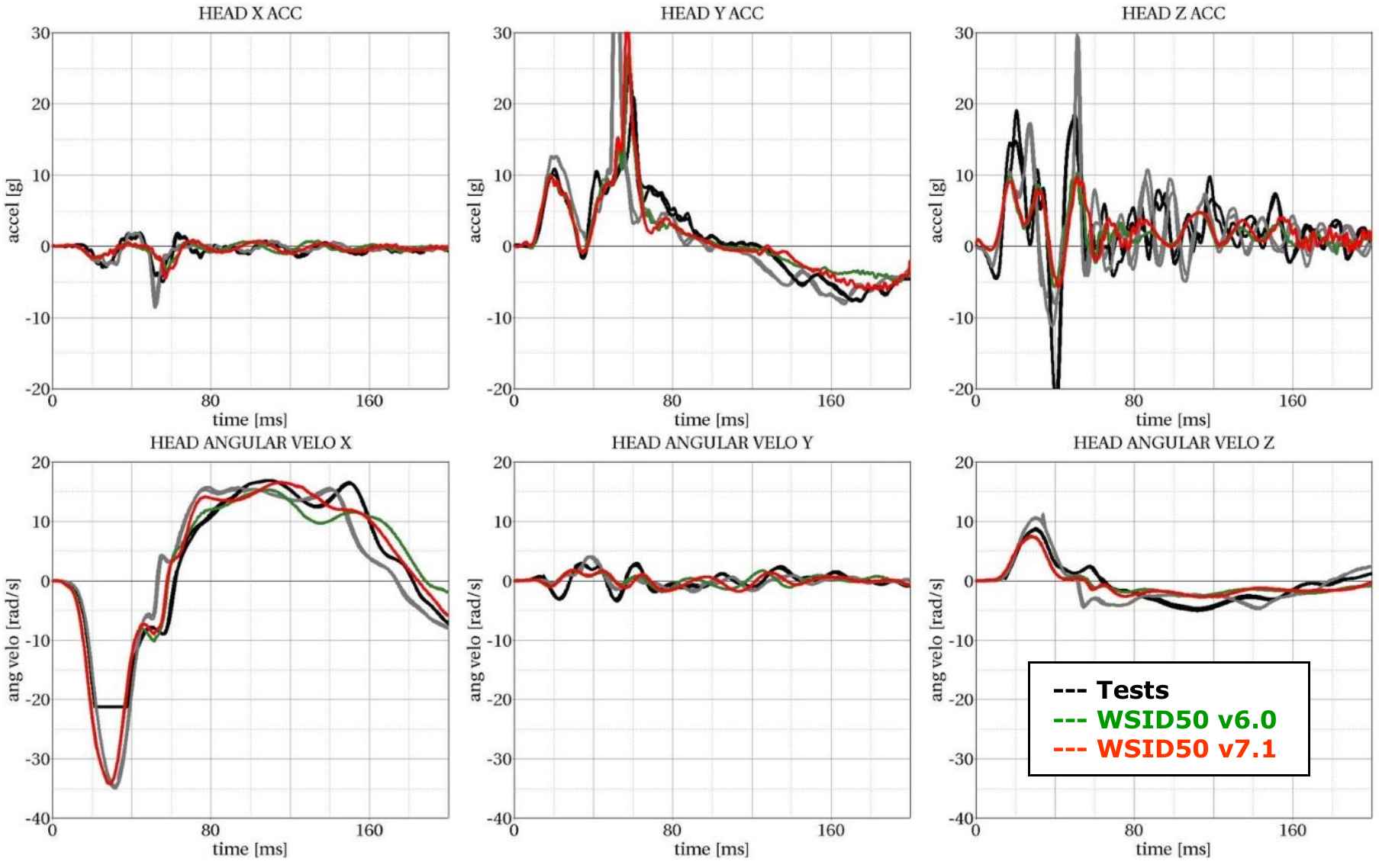
Results of 75 degree, 20g configuration:
Results of 75 degree, 35g configuration:
